Logistics center
Task
The warehousing area of a logistics centre needs to be illuminated with a continuous lighting system. The lighting needs to be switched on and off fully automatically via integrated motion detectors in the shelf aisles, driveways, and in the order-picking areas. The assigned lighting switches on when staff enter the respective sensor’s detection field. When no more movement is detected, the lighting is dimmed down to a lower illumination level after an adjustable period of time has elapsed. It then switches off entirely a short time later. In addition, the entire lighting can also be switched on and off by area via push-buttons at the two side entrances and via control panels on a web visualisation system. The switching status and error messages relating to the entire lighting system are also displayed on corresponding interfaces of the web visualisation system.
Since this is a rented storage space and a future change of use is possible with, e.g., a modified shelf arrangement, within the lighting control solution, it needs to be possible to flexibly arrange the luminaires and sensors in each continuous lighting systems as well as to freely group and allocate them. Therefore, each component has to appear as a separate address in the bus system. Occupants need to be able to measure the energy consumption of the entire lighting solution or parts of it. Further, it has to be possible to display these values in a web visualisation for further evaluation and documentation. You can configure the entire system, each individual luminaire, and the lighting control components such as push-button couplers and motion sensors via an Ethernet connection and a web browser-based configuration interface on a PC. This also enables remote access, remote maintenance, and connection to the higher-level building management system.
APCON solution
The RIDI LINIA continuous lighting systems are equipped with DALI LED gear trays and APCON DALI sensors. The continuous lighting systems and the two APCON push-button couplers are divided up into 5 separate DALI circuits, which are themselves routed to the APCON UNLIMITED lighting control panel. In addition to the peripherals, this lighting control cabinet contains the actual PLC node with the controller to which all the DALI circuits, i.e. all the DALI devices are connected. This PLC is accessed via Ethernet with a web browser on
the PC. The entire lighting system, each individual LED gear tray, each APCON push-button coupler, and each sensor can be configured via the web interface. The energy consumption for the entire lighting system or parts of it can be displayed on another web interface. The data that is generated can then be used for further evaluation and documentation. The integrated Ethernet interface or specific gateways enable a connection to the higher-level building management system, also allowing remote access and maintenance. The LINIA LED gear trays, the APCON push-button couplers, and the APCON DALI sensors can be freely positioned, grouped, and assigned across all RIDI LINIA continuous lighting systems and across all 5 DALI circuits, so that the lighting and lighting control solution can be adapted accordingly in the event of changes of use such as a change in the way the shelves are arranged. Motion detection in the shelf aisles, the two order-picking areas, and the driveways always follows the same principle.
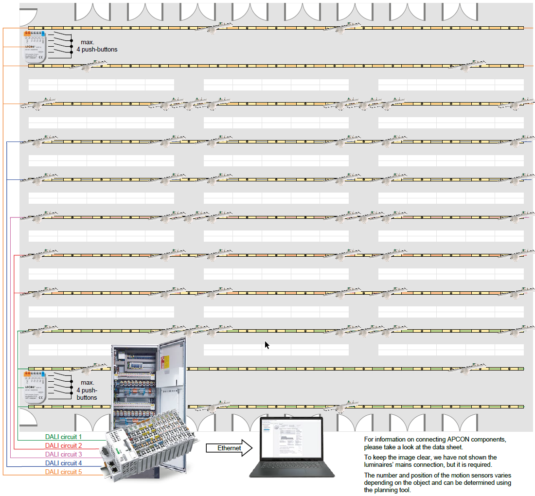
When movement is detected within the detection fields of the APCON sensors, the assigned lighting is switched to its highest illuminance level fully automatically. Once the movement has ceased and after an adjustable period of time has elapsed, the lighting is dimmed to a reduced illumination level before going out completely after a further delay. Movements along the ends of the shelf aisles can be removed from the detection zones by limiting the area that the sensors monitor. Using the two APCON push-button couplers in the installation boxes behind the installed push-buttons (max. 4 push-buttons can be connected potential-free), areas covered by luminaires or groups of luminaires can be switched on and off in addition. Status messages such as switching statuses or possible failures of individual LINIA LED gear trays or groups can be displayed via a visualisation in the web browser on a PC. It is also possible to operate individual gear trays and entire areas via web visualisation.